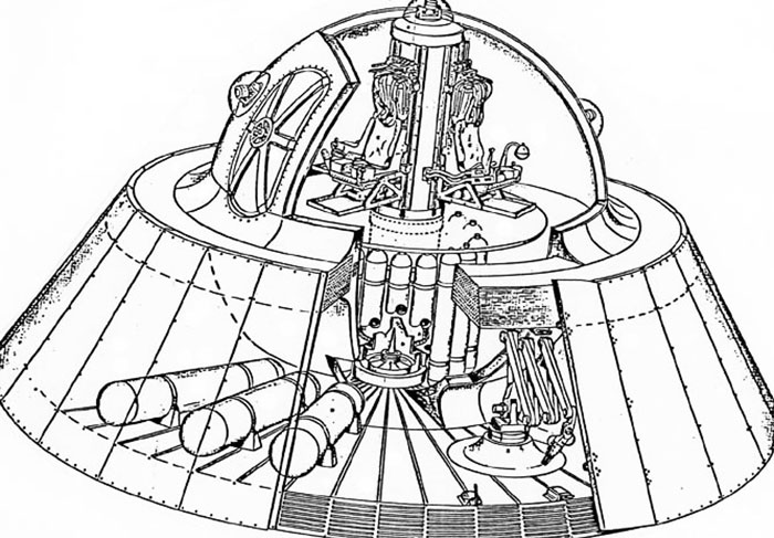
Artists conception of the “Flux Liner” as rendered by Mark McCandlish
The above drawing was made by aerospace illustrator Mark McCandlish who based his sketch on the testimony of a friend of his who witnessed several such craft in operation. On November 12, 1988 his friend had the good fortune of viewing this vehicle and two other electrogravitic craft in a restricted hanger at Norton Air Force base while attending an air show that day. They had diameters of 24 feet, 60 feet, and 130 feet. The crafts were being demonstrated to a select group of people who were given special access at the show. He observed them silently hovering a few feet above the ground. McCandlish made a testimony about this at Steven Greer’s Disclosure press conference held at the Washington DC National Press Club in December 2000. Background information about his disclosure can be found here: https://www.youtube.com/watch?v=Z4yhE1l0CcY. I happened to be present at that conference and had the opportunity of meeting Mark.
Here I will attempt to offer some insights as to how such a vehicle might function. The vehicle has been alternately dubbed the “Alien Reproduction Vehicle”. However, in my opinion there are some aspects which raise questions as to whether the craft is of ET origin. The indication that the vehicle had riveted steel plates, a hatch with a wheel lock similar to a World War I submarine, as well as the general design of the vehicle’s seats and mechanical components resembles manmade construction used prior to World War I. Recent disclosures indicate that advanced propulsion vehicles were in fact being researched in the U.S. as early as the beginning of the 20th century and in Germany prior to the rise of the Nazi regime. But Mark reports that the craft used fiber optic cables presumably with optical sensors to control its pitch and yaw. Also through email communication he told me that the crew compartment is probably fabricated of carbon or kevlar filament. Also he said that the coil section and capacitor plate sections are both embedded in a type of optically clear Herkimer Quartz diamond. The capacitor plates, he said, are a foil lamination made of a Dow Chemical alloy (AZ31-X) that is 95% magnesium and 5% zinc, bonded with molten bismuth, then skinned in a thin copper cladding. Also the side panels and oxygen tanks are all made of composite material. He did not tell me where he got these details, for they were not disclosed in his 2000 white paper. Anyway, this new information suggests that these Flux Liners were built post WWII, possibly after the 1950’s. Mark reports that one air force officer had a chance to see one of these vehicles as early as 1973.
I agree with Mark McCandlish that the vehicles are electrogravitic in nature and that the capacitor plates at the bottom of the vehicle, which are divided in 24 sections, function as electrogravitic thrusters similar to the gravitater capacitors developed by T. Townsend Brown. There is also a coil of many turns of thick copper wire positioned near the top of the frustrated cone hull. McCandlish has suggested that this may be part of a Tesla coil for developing the needed high voltages to power the capacitor plates. However, I believe them to be an integral part of an electrogravitic tank circuit propulsion drive.
Electrogravitic capacitors must be alternately charged and discharged in order to maintain a gravitic thrust toward their positive pole. This is because with a DC charging of the plates, the dielectric eventually polarizes, and produces an electrogravitic force opposite to the initial direction, cancelling out the overall developed force. Brown discovered this in his early electrogravitic experiments; as described in Secrets of Antigravity Propulsion. Repeated charging from zero to maximum applied voltage may be accomplished by polarizing the dielectrics of the capacitors with a DC voltage V, applied in a particular direction, and then applying an AC field to the plates having a voltage equal to that of this pre-applied bias field. As a result, the voltage on the capacitors will alternate between zero and twice the voltage (2V).
This AC alternating field is best accomplished by connecting the capacitors in parallel with a coil to form a tank circuit. The diagram below illustrates one type of tank circuit arrangement. In another design, the current would alternately flow between two capacitors; see second circuit diagram below.
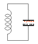

Tank circuit with two capacitors
As a result, the voltage on one capacitor would approach zero as the voltage on the partner capacitor approaches a maximum. This oscillation would be accomplished by exciting the tank circuit with an oscillator tuned close to the tank circuit’s resonant frequency.
A given set of partner capacitors could be adjacent to one another with a total of 12 sets completing the circle around the craft. A separate coil could be dedicated to each such capacitor plate set. In a given set, one capacitor bank would be attaining a maximum voltage while its adjacent capacitor bank attained its minimum voltage. As a result, the voltage on these sectors would circumferentially oscillate to set up a rotary electrogravitic wave that would travel around the perimeter of the craft. This rotating electrogravitic field could effectively shield the craft from the Earth’s gravitational pull by redirecting the normally downward terrestrial G-etheron flow in a horizontal direction, e.g. outward rather than downward, thereby reducing the local gravity pull. This would be a secondary effect that would assist the upward electrogravitic propulsive effect produced by the capacitor bank.
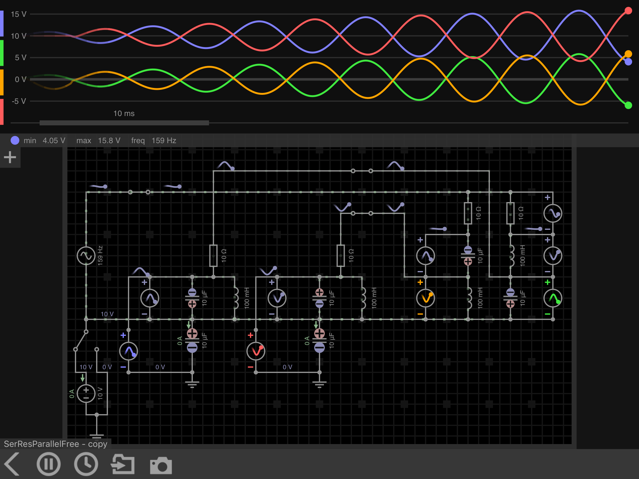
Lee Dickenson suggests using the following tank circuit; see diagram below (a revision of his previous diagram updated to include d.c biasing, with two series resonators with outputs phase shifted 180°).
He wrote to me the following. If anyone has any questions about his circuit, he can be contacted by answering his posting below.:
The name “Flux Liner” is appropriate for this vehicle since it must maintain an electric flux in its tank circuits consisting of the capacitor pairs and a coil. The name flux capacitor from the movie Back to the Future also comes to mind as an appropriate designator for its capacitor system.
I agree with Mark that the Flux Liner accomplishes its steering by applying more or less voltage to certain capacitor sectors, e.g., more on one side of the craft as opposed to the other side. In the context of the above-suggested propulsion method, one way this could be accomplished is by arranging that power be added to an extra capacitor layer in the stack of capacitor plates. Perhaps the lower most capacitor plate layer could function as a steering plate. Several sectors on one side of the craft could have their lower plate energized along with the other plates, thereby increasing the overall thrust on that side. This could be accomplished easily by use of a vacuum switch which when activated would connect the lower plate in parallel with the plates above it in its stack. But there may be a more feasible way to accomplish this steering, as described below.
The Flux Liner may not need a Tesla coil to achieve its high voltage. This could be accomplished just by the tank circuit itself. Tank circuits have the ability to progressively increase their voltage from an initially low voltage to a very high voltage during their course of oscillation provided that they are excited at their resonant frequency. High-Q tank circuits can potentially achieve voltages 1000 fold higher than their excitation voltage. Hence a 10,000 volt oscillator circuit could excite its tank circuit to yield 10 million volt potentials across the vehicle’s capacitor plates.
This brings up an alternate method for steering the vehicle. If each pair of capacitor plate sectors were connected through a dedicated coil, with 12 coils being used for the 24 capacitor sectors, then these sectors could be separately excited by 12 oscillators. Selecting a frequency that was tuned closer to the resonant frequency of a certain plate sector tank circuit would preferentially boost the power to that set of plates, thereby increasing their thrust compared to other tank circuit plate sections. Thus steering could be accomplished simply with the use of 12 low frequency audio oscillators whose frequency was slightly varied relative to the tank circuit resonant frequency. The same method could be used to increase the vehicle’s upward thrust. As the capacitor banks are excited close to their resonant frequencies, they will achieve higher voltages and hence greater electrogravitic thrust.
One thing that points to a possible earlier construction date for these vehicles is that they use thick copper wire or copper tubes for their coils rather than high temperature superconducting wire. The designers of this craft would have wanted to minimize the resistance of their tank circuits in order to maximize their resonant Q factor and hence the achievable voltage amplification. The fact that they did not indicates that they were designed in an era prior to the discovery of high temperature superconductors. Copper oxide superconductors capable of working at liquid nitrogen temperatures were not discovered until 1986. In 1973, the earliest date we have when someone viewed these craft, superconductors were able to function at temperatures only as high as 23 K, which implies the need for liquid helium cooling. That the designers of this craft could achieve the observed performance without the use of superconductors is quite amazing.
More about T. Townsend Brown’s seminal work may be found in my book Secrets of Antigravity Propulsion.
A minimum of 1.25e6V, a microwave range, a disruptive/turbulent EM field.
Hello Mr. LaViolette
You said the Flux Liner has quartz diamonds, what is their function? From the very limited information I found about the Krosky/Frost experiment that it is claimed that the weight of quartz crystal can be nullified by exciting it. Do you think they may be used for the same purpose here? If not, what are they used for?
Have any back-of-the-napkin computations been carried out for the Tesla coil at the top of the cone? I know how a toroidal coil works. What’s the math for the non-toroidal coils running longitudinally?
Looking to buy one or more copies (blueprints) for Mark’s drawing. I tried to email him to no avail. Any help would be appreciated.
Thank you
Try Tom Valone. He may have more contact with him.
Paul. Thank you for brilliant suggestions. However regarding the need for superconducting materials for coils… once you’ve built one. At least in my case. My system (and Teslas) are longitudinal electric induction. Not magnetic and thus they operate COLD. Also although you can use magnetism for inertialess propulsion (There are three independent ways I know of) YOU DEFINITELY DO NOT WANT TO EXPOSE LIVING TISSUE TO THAT METHOD!! Materials can become translucent/invisible and if the field changes while two different materials are in the same space THEY BECOME ONE!!!! as per horror stories of the Philadelphia experiment. Magnetic vorticity is what bonds atoms into molecules and prevents you from walking through a wall. Not the latent longitudinal electric force. Using magnetic induction is waste full anyways. Conventional DC/A.C. electrical current is changing a copper wire into a temporary magnet. With two counter rotating flows moving In opposite direction through its length. No different than trying to force two streams of water in opposite direction thru one pipe like winding snakes in opposite direction. This is why the wire gets hot. Has resistance and self destruct when it reaches saturation. Longitudinal current has NO POSITIVE and negative moving in opposite directions. It is either ramming (sending pressure waves) down a pipe full water and collecting All the energy at the other end without friction (In the case of high voltage short pulse) AND BTW you can pick up radial inductive current off the length of the wire radially hence the magnifying pancake coil. Or you have two containers joined by a siphon and you lift them up down alternately. Both are friction less with electricity and you alwAys route it bAck and forth thru your spiral amplifier anyways which gives you wave length. The biggest problem is damping down the power. Not making it. All you need is a tiny imbalance and if you are not carefully it runs away and destroys itself. ALL environmental energy harvesters Require Governer systems. If built right(follow pi and golden ratio where applicable) and all good systems will quickly destroy themselves. Resistance is something YOU MUST HAVE. and is how you regulate if it’s not a percentage only feedback system.
Hi Golden boy,
Thank you your reply!
Dr Paul LaViolette passed away on 19 December 2022. The people, eg. Model G Vortical Motion Group, and other friends and colleagues of Paul, who have worked with him over the last 5 years and longer, are continuing his work at the Starburst Foundation, and maintaining his websites: https://starburstfound.org/ and https://etheric.com/ .
Best,
Brendan
What you think about the central column? It must be a spark discharge to increase the electrogravitic effect? I know that an electric discharge can create a electrogravitic impulse wave that can provide a force greater than you get from simple capacitors. What you think about that?
Reverse Ion and Gamma radiation chamber. Both can now be manipulated in ways you cant imagine.
hello, my project for an electrogravitational engine based on the effect of T T Brown, which is developing the lifter technology of an asymmetric capacitor. It is, in general, a powerful asymmetrical high voltage capacitor with a solid dielectric, which can be ceramic, quartz, porcelain, and so on. The purpose of this capacitor is as a “big lifting
force” engine that can be placed on everything from a stool to a car, a truck, etc., taking into account the necessary safety and installation techniques. The capacitor is designed to operate in a resonant circuit of thea defined frequency, composed of an inductance with a high quality factor at the expense of the mass (according to preliminary data of the ratio of the inductive force / mass of inductance and others is
acceptable). In the figures, using the Solidworks program software, I designed an example design of one of the my models in two variants, one with a ceramic dielectric and the other with a quartz dielectric. The configuration shows, that i have adhered to the basic idea and principle of the lifters, but in fact this is just one option, it is important to observe the asymmetry between the two electrodes (and dielectrics in some cases). In this case, the ceramic or quartz dielectric completely encompasses the two asymmetric capacitor electrodes, the ceramic body is ceramic, and the electrodes are thin and wide ring-shaped because of the high frequency and the large reactive currents, and the body thickness is adapted to the working voltage at 1000V per 1mm. This concept is a prototype and idea for creating and implementing electrogravitational technology for a public and mass transport, as technology is safe, reliable, efficient and inexpensive compared to other very diverse examples in this area, perhaps have no analogue.
and short video:https://youtu.be/5hEJOwwn4-Y
if you were building a similar vehicle today how would you change the design, using all that is known at this point. I would love to hear your ideas.
I have nothing more to add than what was stated in the posting.
In your article you mention 1973 as the first reported observation. However a first or second generation ARV was photographed by Harvey Williams of the USAF in 1966 over Provo, Utah. That would be seven years prior. How might that impact your thesis from a technological viewpoint?
The capacitor section in the ARV merely achieves a steering effect for the device which has already been “mass-cancelled” by the mercury vapour turbine in the middle (compare “The Nazi Bell”).
The electrogravitics system only assists in the overall system.
Mark pointed this out in multiple presentations, as we’ll as podcasts. Trying to achieve the ARV’s performance attributes only via Biefeld-Brown is a fallacy, and a distraction.
I don’t think we are in a position to make such cut and dry claims when none have made an attempt to reproduce this vehicle.
Dear Paul,
I’ve read your electrogravitic book many years ago & I think you are on the right track with most things.
After running a few simple resonator circuits you find that a parallel resonator capacitor & inductor combination has max impedance & acts as a near open circuit load at resonance & the voltage source feed appears on the output. No voltage gain or build up of source to output voltage. However, if you build a series resonator Resistor, capacitor & inductor at resonance it looks purely resistive as the reactive components L & C cancel like a short but the voltages build and can be orders of magnitude above the excitation voltage but cancel out. The trick is to put the parallel resonator circuit across either of the limbs of the series inductor or capacitor, as the parallel resonator has near infinite impedance it doesn’t load the series stage & you’ve got your parallel oscillator at high voltage driven by the series resonator, connect many parallel resonators from one series source. Resonant frequencies of parallel & series resonators are tuned to the same frequency.
If you have an email I can post you a schematic.
Hope this helps.
Lee, Thank you for your informative research. Your schematic and your explanation has been added to the post. Could you explain where the adjacent pairs of electrogravitic capacitor plates would be in your diagram. And, would your circuit energize them so that one capacitor plate was at its voltage max when the adjacent one was at its voltage minimum?
Re: Tank Circuit Control – Electrogravitics. Rev’1′
Dear Paul,
I’ve updated the circuit to include d.c biasing, two series resonators with outputs phase shifted 180deg. Output parallel resonators are alternating 180deg out of phase and the d.c. offset at 10v midpoint allows the swing 0v to 2Vs top plate relative to the bottom plate by using another capacitor. Using the small signal model we have 1V a.c input building and scaling to 10v a.c. then 20v to 0v d.c. offset a.c. relative to bottom plate.
Freewheeling mode added by switching off the Vin of 1V a.c. then isolating the outputs of the parallel resonators. These are ideal components and series resistance within the inductors will damp the oscillation before re-exciting.
The whole concept is to be scaled to high frequencies and kV voltage range.
The parallel resonators are arranged alternative pairs and symmetrically around the craft, there is always a high positive voltage on one set of top capacitor plates when there is a zero voltage on the other set of top capacitor plate alternating.
I hope this helps.
I sent you the circuits for review.
Hello Dr. Laviolette,
I’m a researcher based in Canada and I’m interested in starting a community of researchers who could share their findings on ARV technology, similar to the “open source” model of sharing software code. Are there researchers in the western United States or western Canada whom I can contact to work on aspects of the ARV?
currently, I’m interested in designing the tank circuit, and I’ve read your book. But I don’t know where to start, so it would be great to talk to other researchers in my area. Thanks.
Dr. Laviolette,
Can you verbally describe, or somehow show for me how the circuit should be connected utilizing this two capacitor tank circuit to drive a four thruster system? Also, if the tank circuit were excited at it’s resonant frequency, could the voltage somehow be governed to hold at 100 kv? and would it then become unnecessary to use a Tesla-coil for a/c voltage multiplication? Lastly, what type of oscillator would be practical and tunable for an application like this? Thank you so much for any help you can offer to point my understanding of these things in the right direction, if these are stupid impossible questions… just say so. God bless you my friend!
Sorry that I cannot offer help on this. I suggest you read the Radio Amateur’s Handbook or contact a friend who has experience in radio electronics.
I was out late one weeknight (3am) with a friend in Central Indiana in 2001. We were in her car (she was driving) on a country road that runs through miles of corn fields.
Rarely am I passenger in a car, so I was taking in the sights from the passenger seat. In the distance I noticed a lighted object taking flight from the ground. Rising at an angle like planes at an airport do. Had to be a few miles away. It took me a minute to realize that there were no airports out there. Nothing but corn fields as I mentioned. That’s when I really took notice.
I brought the object to her attention and asked her to pull over so we could check it out. So we pull over on the side of this road and turn the car off. It’s very dark with the cars lights off. We can’t be seen.
We watched as the object got closer to our area. It took it about 2 minutes to get to us. As it was approaching we noticed the lights on the object were multicolored. Red green yellow blue etc. And it was a disc! Just like you see in the movies. At its closest point, it couldn’t have been but 100 feet above our heads. Lights glowing and just floating along slowly and whisper quiet.
At this point she starts getting scared and begins to get upset. I was intrigued and not afraid in the least. So I assured her everything was gonna be ok. So at this point, about a mile or so away we notice another car heading in our direction on the country road. And all of the sudden the craft (still overhead mind you) just powers down all of its lights in what I can assume was an attempt to remain unseen.
Yet there her and I are, seemingly unnoticed, right below the craft. As its lights were powered down I could still see it due to the reflection of the moon on its silvery metal. It was faint but I could catch reflections here and there as it slowly meandered.
The other car passed us and didn’t notice a thing. After a few more minutes the craft was out of range so we just started the car up and proceeded on.
A few days later a relative of mine came in for the weekend to visit his folks who lived in this area. He just happened to be a soldier stationed at Wright Patterson in Ohio. So when I saw him I told him of what I saw. Just thinking he would blow it off and that would be that.
However, he immediately asked me to take him out to where we had seen the craft. So I did. I took him to the exact spot. While we were out there I asked him what he thought it was as I suspected it was one of “our” craft. Nothing extraterrestrial at all. He looked at me and said, “Well you know Wright Patterson is not far at all from here as the crow flies.” So we got back in the car and headed off. And that was that.
Just thought I would share 🙂
I’m sorry, I know there are far to many acronym’s out there. I was referring to the Lafforgue field propulsion thruster, and I’m curious if the two capacitor tank circuit described in your article on the flux liner, could be wired to drive a four capacitor Lafforgue system using one coil for each pair of thrusters? This would be in place of the standard parallel tank circuit?
Thank you for your advice.
Emanuel
Yes, it should work just as well with the Lafforgue thruster.
Dr. Laviolette,
would the two capacitor tank circuit you’ve shown work for a four capacitor A/C LFPT system, utilizing one inductor for each pair of LFPT’s ?
Thank you for all that you do sir, I so do appreciate hearing the truth for a change. How very refreshing!
God’s richest blessings on you Dr. Paul.
I don’t understand your question. What is an LFPT?
Thank you for your appreciation.
Reading your comments is very interesting, Mr LaViolette. One thing with Marks ARV is, should’nt the capacitors be asymmetric instead of symmetric? So that an imbalance in the electric field between the plates causes the craft to move in the direction of the smaller plate? Or have I missed something?
No this is not an asymmetric thruster; this is an electrogravitic thruster based on Brown’s early research with gravitators. The propulsion is due to a generated gravitational force, rather than to imbalanced electrical forces. Brown experimented with both concepts.
No, this is an electrogravitic drive, not an unbalanced force drive.
I like your work mr Laviolette but allow me please to be sceptical about this one. Too few to no proofs are given for the existence of this vehicle and of that “super secretive show”. One could blame you for being a simple ufologist…. .
We have eye witness accounts from trustworthy witnesses. That is the best we can hope for in the present case. If you want to call me a ufologist, fine. I believe that such advanced propulsion vehicles exist, as you can see from my most recent book on the subject. Anyway I believe that the coil-capacitor design I describe should develop a sizable lift force and is worth duplicating by prospective researchers.